


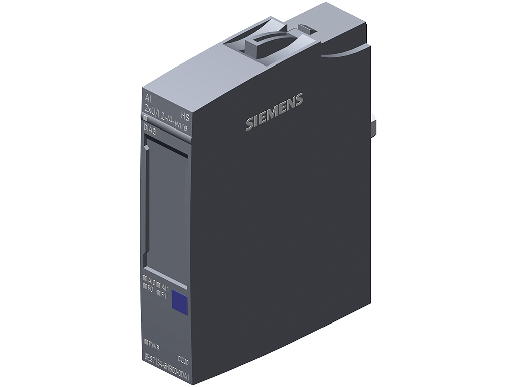
SIMATIC ET 200SP, Analog input module, AI 2x U/I 2-/4-wire High Speed, suitable for BU type A0, A1, Color code CC00, channel diagnostics, 16 bit, +/-0.3%
6ES7134-6HB00-0DA1 là module mở rộng đầu vào tương tự (analog input module) cho ET 200SP (CPU) được hãng SIEMENS sản xuất & phát triển với thương hiệu SIMATIC. AI 2xU/I 2-/4-wire HS SIMATIC ET 200SP 6ES7134-6HB00-0DA1 được SIEMENSIM phát triển và phân phối rộng rãi trên thị trường Việt Nam. Nếu quý khách hàng đang có nhu cầu cần tư vấn, báo giá hay mua 6ES7134-6HB00-0DA1 thì hãy liên hệ Siemens Industry Mall để được hỗ trợ một cách tận tâm, nhanh chóng và hiệu quả nhé.
Mục lục
Tóm tắt thông số kỹ thuật 6ES7134-6HB00-0DA1
| Mã sản phẩm | 6ES7134-6HB00-0DA1 |
| Dòng sản phẩm | SIMATIC ET 200SP, AI 2xU/I 2-/4-wire HS |
| Hãng sản xuất | SIEMENS |
| Số lượng đầu vào analog | AI 2x U/I 2-/4-wire |
| Nguồn cung cấp | 24 V DC (19.2 – 28.8 V DC) |
| Kích thước (RxCxS) | 15 x 73 x 58 mm |
| Trọng lượng | 32 g |
Chi tiết thông số kỹ thuật 6ES7134-6HB00-0DA1
Tải về datasheet (pdf): Tại đây!
| General information | |
| Product type designation | AI 2xU/I 2-/4-wire HS |
| HW functional status | From FS07 |
| Firmware version | |
| ● FW update possible | Yes |
| usable BaseUnits | BU type A0, A1 |
| Color code for module-specific color identification plate | CC00 |
| Product function | |
| ● I&M data | Yes; I&M0 to I&M3 |
| ● Isochronous mode | Yes |
| ● Measuring range scalable | No |
| ● Scalable measured values | No |
| ● Adjustment of measuring range | No |
| Engineering with | |
| ● STEP 7 TIA Portal configurable/integrated from version | V13 SP1 |
| ● STEP 7 configurable/integrated from version | V5.5 SP3 / – |
| ● PROFIBUS from GSD version/GSD revision | One GSD file each, Revision 3 and 5 and higher |
| ● PROFINET from GSD version/GSD revision | GSDML V2.3 |
| Operating mode | |
| ● Oversampling | Yes; 2 channels per module |
| ● MSI | No |
| CiR – Configuration in RUN | |
| Reparameterization possible in RUN | Yes |
| Calibration possible in RUN | No |
| Supply voltage | |
| Rated value (DC) | 24 V |
| permissible range, lower limit (DC) | 19.2 V |
| permissible range, upper limit (DC) | 28.8 V |
| Reverse polarity protection | Yes |
| Input current | |
| Current consumption (rated value) | 39 mA; without sensor supply |
| Encoder supply | |
| 24 V encoder supply | |
| ● 24 V | Yes; For current measurement |
| ● Short-circuit protection | Yes |
| ● Output current, max. | 20 mA; max. 50 mA per channel for a duration < 10 s |
| Power loss | |
| Power loss, typ. | 0.95 W; without sensor supply |
| Address area | |
| Address space per module | |
| ● Address space per module, max. | 4 byte; + 1 byte for QI information (32 bytes in the oversampling operating mode) |
| Hardware configuration | |
| Automatic encoding | Yes |
| ● Mechanical coding element | Yes |
| ● Type of mechanical coding element | Type A |
| Selection of BaseUnit for connection variants | |
| ● 2-wire connection | BU type A0, A1 |
| ● 4-wire connection | BU type A0, A1 |
| Analog inputs | |
| Number of analog inputs | 2; Differential inputs |
| ● For current measurement | 2 |
| ● For voltage measurement | 2 |
| permissible input voltage for voltage input (destruction limit), max. | 30 V |
| permissible input current for current input (destruction limit), max. | 50 mA |
| Cycle time (all channels), min. | 125 µs |
| Analog input with oversampling | Yes |
| ● Values per cycle, max. | 16 |
| ● Resolution, min. | 50 µs |
| Input ranges (rated values), voltages | |
| ● 0 to +10 V | Yes; 15 bit |
| — Input resistance (0 to 10 V) | 75 kΩ |
| ● 1 V to 5 V | Yes; 13 bit |
| — Input resistance (1 V to 5 V) | 75 kΩ |
| ● -10 V to +10 V | Yes; 16 bit incl. sign |
| — Input resistance (-10 V to +10 V) | 75 kΩ |
| ● -5 V to +5 V | Yes; 15 bit incl. sign |
| — Input resistance (-5 V to +5 V) | 75 kΩ |
| Input ranges (rated values), currents | |
| ● 0 to 20 mA | Yes; 15 bit |
| — Input resistance (0 to 20 mA) | 130 Ω |
| ● -20 mA to +20 mA | Yes; 16 bit incl. sign |
| — Input resistance (-20 mA to +20 mA) | 130 Ω |
| ● 4 mA to 20 mA | Yes; 14 bit |
| — Input resistance (4 mA to 20 mA) | 130 Ω |
| Cable length | |
| ● shielded, max. | 1 000 m; 200 m for voltage measurement |
| Analog value generation for the inputs | |
| Measurement principle | Actual value encryption (successive approximation) |
| Integration and conversion time/resolution per channel | |
| ● Resolution with overrange (bit including sign), max. | 16 bit |
| ● Interference voltage suppression for interference frequency f1 in Hz | No |
| ● Conversion time (per channel) | 10 µs |
| Smoothing of measured values | |
| ● Number of smoothing levels | 7; none; 2-/4-/8-/16-/32-/64-fold |
| ● parameterizable | Yes |
| Encoder | |
| Connection of signal encoders | |
| ● for voltage measurement | Yes |
| ● for current measurement as 2-wire transducer | Yes |
| — Burden of 2-wire transmitter, max. | 650 Ω |
| ● for current measurement as 4-wire transducer | Yes |
| Errors/accuracies | |
| Linearity error (relative to input range), (+/-) | 0.03 % |
| Temperature error (relative to input range), (+/-) | 0.01 %/K |
| Crosstalk between the inputs, min. | -50 dB |
| Repeat accuracy in steady state at 25 °C (relative to input range), (+/-) | 0.1 % |
| Operational error limit in overall temperature range | |
| ● Voltage, relative to input range, (+/-) | 0.3 % |
| ● Current, relative to input range, (+/-) | 0.3 % |
| Basic error limit (operational limit at 25 °C) | |
| ● Voltage, relative to input range, (+/-) | 0.2 % |
| ● Current, relative to input range, (+/-) | 0.2 % |
| Interference voltage suppression for f = n x (f1 +/- 1 %), f1 = interference frequency | |
| ● Common mode voltage, max. | 35 V |
| ● Common mode interference, min. | 90 dB |
| Isochronous mode | |
| Filtering and processing time (TCI), min. | 80 µs |
| Bus cycle time (TDP), min. | 125 µs; Starting from firmware Version V2.0.1 |
| Interrupts/diagnostics/status information | |
| Alarms | |
| ● Diagnostic alarm | Yes |
| ● Limit value alarm | Yes; two upper and two lower limit values in each case |
| Diagnoses | |
| ● Wire-break | Yes; channel-by-channel, at 4 to 20 mA only |
| ● Short-circuit | Yes; channel-by-channel, at 1 to 5 V or for current measuring ranges short-circuit in encoder supply |
| ● Group error | Yes |
| ● Overflow/underflow | Yes |
| Diagnostics indication LED | |
| ● Monitoring of the supply voltage (PWR-LED) | Yes; green PWR LED |
| ● Channel status display | Yes; green LED |
| ● for channel diagnostics | Yes; red LED |
| ● for module diagnostics | Yes; green/red DIAG LED |
| Potential separation | |
| Potential separation channels | |
| ● between the channels | Yes |
| ● between the channels and backplane bus | Yes |
| ● between the channels and the power supply of the electronics | Yes |
| Isolation | |
| Isolation tested with | 707 V DC (type test) |
| Ambient conditions | |
| Ambient temperature during operation | |
| ● horizontal installation, min. | -30 °C |
| ● horizontal installation, max. | 60 °C |
| ● vertical installation, min. | -30 °C |
| ● vertical installation, max. | 50 °C |
| Altitude during operation relating to sea level | |
| ● Installation altitude above sea level, max. | 5 000 m; Restrictions for installation altitudes > 2 000 m, see manual |
| Dimensions | |
| Width | 15 mm |
| Height | 73 mm |
| Depth | 58 mm |
| Weights | |
| Weight, approx. | 32 g |
Phân phối & báo giá 6ES7134-6HB00-0DA1
Nếu quý khách hàng đang có nhu cầu cần tư vấn, báo giá hay mua 6ES7134-6HB00-0DA1 thì hãy liên hệ Siemens Industry Mall để được hỗ trợ một cách tận tâm, nhanh chóng và hiệu quả nhé.