


SIMATIC S7-1500 Analog input module, AI 8xU/I/R/RTD BA, 16 bit resolution, Accuracy 0.5%, 8 channels in groups of 8; Common mode voltage 4 V DC, Diagnostics; Hardware interrupts; Delivery including infeed element, shield bracket and shield terminal: Front connector (screw terminals or push-in) to be ordered separately
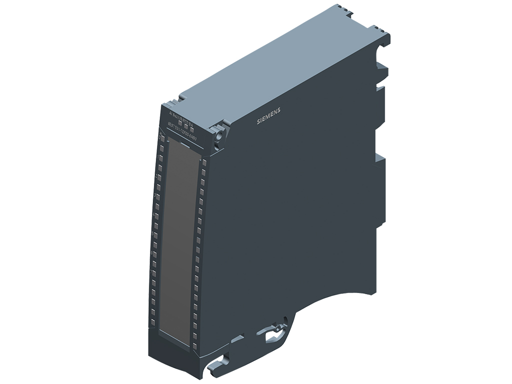
6ES7531-7QF00-0AB0 là mô đun mở rộng tín hiệu ngõ vào tương tự cho PLC S7-1500 (CPU) do hãng SIEMENS phát triển & sản xuất với thương hiệu SIMATIC thuộc họ S7-1500. SM 531 AI 8xU/I/R/RTD BA 16-bit SIEMENS 6ES7531-7QF00-0AB0 được SIEMENSIM.COM phát triển và phân phối rộng rãi trên thị trường Việt Nam. Nếu quý khách hàng đang có nhu cầu cần tư vấn hay mua 6ES7531-7QF00-0AB0 thì hãy liên hệ SIEMENS INDUSTRY MALL để được hỗ trợ một cách tận tâm, nhanh chóng và hiệu quả nhé.
Mục lục
Tóm tắt thông số kỹ thuật 6ES7531-7QF00-0AB0
| Mã sản phẩm | 6ES7531-7QF00-0AB0 |
| Dòng sản phẩm | SIMATIC S7-1500, SM 531 |
| Hãng sản xuất | SIEMENS |
| Số lượng đầu vào tương tự | 8 AI U/I/R/RTD BA, 16 bit |
| Nguồn cung cấp | 24 V DC (20.4-28.8 V DC) |
| Kích thước (RxCxS) | 35x147x129 mm |
| Trọng lượng | 250 g |
Chi tiết thông số kỹ thuật 6ES7531-7QF00-0AB0
Tải về datasheet (pdf): Tại đây!
| General information | |
| Product type designation | AI 8xU/I/R/RTD BA |
| HW functional status | FS01 |
| Firmware version | V1.0.0 |
| ● FW update possible | Yes |
| Product function | |
| ● I&M data | Yes; I&M0 to I&M3 |
| ● Prioritized startup | No |
| Engineering with | |
| ● STEP 7 TIA Portal configurable/integrated from version | V15.1 / V16 |
| ● STEP 7 configurable/integrated from version | V5.5 SP3 / – |
| ● PROFIBUS from GSD version/GSD revision | V1.0 / V5.1 |
| ● PROFINET from GSD version/GSD revision | V2.3 / – |
| Operating mode | |
| ● Oversampling | No |
| ● MSI | Yes |
| CiR – Configuration in RUN | |
| Reparameterization possible in RUN | Yes |
| Calibration possible in RUN | No |
| Power | |
| Power available from the backplane bus | 0.85 W |
| Power loss | |
| Power loss, typ. | 0.9 W |
| Analog inputs | |
| Number of analog inputs | 8 |
| ● For current measurement | 8 |
| ● For voltage measurement | 8 |
| ● For resistance/resistance thermometer measurement | 8 |
| permissible input voltage for voltage input (destruction limit), max. | 12 V; 12 V continuous, 30 V for max. 1 s |
| permissible input current for current input (destruction limit), max. | 40 mA |
| Constant measurement current for resistance-type transmitter, typ. | 230 … 370 µA |
| Technical unit for temperature measurement adjustable | Yes; °C/°F/K |
| Input ranges (rated values), voltages | |
| ● 0 to +5 V | No |
| ● 0 to +10 V | No |
| ● 1 V to 5 V | Yes |
| — Input resistance (1 V to 5 V) | 10 MΩ |
| ● -1 V to +1 V | Yes |
| — Input resistance (-1 V to +1 V) | 10 MΩ |
| ● -10 V to +10 V | Yes |
| — Input resistance (-10 V to +10 V) | 10 MΩ |
| ● -2.5 V to +2.5 V | No |
| ● -25 mV to +25 mV | No |
| ● -250 mV to +250 mV | No |
| ● -5 V to +5 V | Yes |
| — Input resistance (-5 V to +5 V) | 10 MΩ |
| ● -50 mV to +50 mV | Yes |
| — Input resistance (-50 mV to +50 mV) | 10 MΩ |
| ● -500 mV to +500 mV | Yes |
| — Input resistance (-500 mV to +500 mV) | 10 MΩ |
| ● -80 mV to +80 mV | No |
| Input ranges (rated values), currents | |
| ● 0 to 10 mA | No |
| ● 0 to 20 mA | Yes |
| — Input resistance (0 to 20 mA) | 25 Ω; Plus approx. 42 ohms for overvoltage protection by PTC |
| ● -20 mA to +20 mA | Yes |
| — Input resistance (-20 mA to +20 mA) | 25 Ω; Plus approx. 42 ohms for overvoltage protection by PTC |
| ● 4 mA to 20 mA | Yes |
| — Input resistance (4 mA to 20 mA) | 25 Ω; Plus approx. 42 ohms for overvoltage protection by PTC |
| Input ranges (rated values), thermocouples | |
| ● Type B | No |
| ● Type C | No |
| ● Type E | No |
| ● Type J | No |
| ● Type K | No |
| ● Type L | No |
| ● Type N | No |
| ● Type R | No |
| ● Type S | No |
| ● Type T | No |
| ● Type U | No |
| ● Type TXK/TXK(L) to GOST | No |
| Input ranges (rated values), resistance thermometer | |
| ● Cu 10 | No |
| ● Cu 10 according to GOST | No |
| ● Cu 50 | No |
| ● Cu 50 according to GOST | No |
| ● Cu 100 | No |
| ● Cu 100 according to GOST | No |
| ● Ni 10 | No |
| ● Ni 10 according to GOST | No |
| ● Ni 100 | Yes; Standard/climate |
| — Input resistance (Ni 100) | 10 MΩ |
| ● Ni 100 according to GOST | No |
| ● Ni 1000 | Yes; Standard/climate |
| — Input resistance (Ni 1000) | 10 MΩ |
| ● Ni 1000 according to GOST | No |
| ● LG-Ni 1000 | Yes; Standard/climate |
| — Input resistance (LG-Ni 1000) | 10 MΩ |
| ● Ni 120 | No |
| ● Ni 120 according to GOST | No |
| ● Ni 200 | No |
| ● Ni 200 according to GOST | No |
| ● Ni 500 | No |
| ● Ni 500 according to GOST | No |
| ● Pt 10 | No |
| ● Pt 10 according to GOST | No |
| ● Pt 50 | No |
| ● Pt 50 according to GOST | No |
| ● Pt 100 | Yes; Standard/climate |
| — Input resistance (Pt 100) | 10 MΩ |
| ● Pt 100 according to GOST | No |
| ● Pt 1000 | Yes; Standard/climate |
| — Input resistance (Pt 1000) | 10 MΩ |
| ● Pt 1000 according to GOST | No |
| ● Pt 200 | No |
| ● Pt 200 according to GOST | No |
| ● Pt 500 | No |
| ● Pt 500 according to GOST | No |
| Input ranges (rated values), resistors | |
| ● 0 to 150 ohms | No |
| ● 0 to 300 ohms | No |
| ● 0 to 600 ohms | Yes |
| — Input resistance (0 to 600 ohms) | 10 MΩ |
| ● 0 to 3000 ohms | No |
| ● 0 to 6000 ohms | Yes |
| — Input resistance (0 to 6000 ohms) | 10 MΩ |
| ● PTC | Yes |
| — Input resistance (PTC) | 10 MΩ |
| Cable length | |
| ● shielded, max. | 200 m; 50 m at 50 mV |
| Analog value generation for the inputs | |
| Measurement principle | integrating |
| Integration and conversion time/resolution per channel | |
| ● Resolution with overrange (bit including sign), max. | 16 bit |
| ● Integration time, parameterizable | Yes |
| ● Integration time (ms) | 2,5 / 16,67 / 20 / 100 ms |
| ● Basic conversion time, including integration time (ms) | 10 / 24 / 27 / 107 ms |
| — additional conversion time for wire-break monitoring | 4 ms (to be considered in R/RTD/U 1 to 5 V measurement) |
| — additional conversion time for resistance measurement | 8 ms |
| ● Interference voltage suppression for interference frequency f1 in Hz | 400 / 60 / 50 / 10 Hz |
| Smoothing of measured values | |
| ● parameterizable | Yes |
| ● Step: None | Yes |
| ● Step: low | Yes |
| ● Step: Medium | Yes |
| ● Step: High | Yes |
| Encoder | |
| Connection of signal encoders | |
| ● for voltage measurement | Yes |
| ● for current measurement as 2-wire transducer | Yes; with external supply |
| ● for current measurement as 4-wire transducer | Yes |
| ● for resistance measurement with two-wire connection | Yes; Only for PTC |
| ● for resistance measurement with three-wire connection | Yes; All measuring ranges except PTC; internal compensation of the cable resistances |
| Errors/accuracies | |
| Linearity error (relative to input range), (+/-) | 0.1 % |
| Temperature error (relative to input range), (+/-) | 0.006 %/K |
| Crosstalk between the inputs, max. | -50 dB |
| Repeat accuracy in steady state at 25 °C (relative to input range), (+/-) | 0.1 % |
| Operational error limit in overall temperature range | |
| ● Voltage, relative to input range, (+/-) | 0.5 % |
| ● Current, relative to input range, (+/-) | 0.5 % |
| ● Resistance, relative to input range, (+/-) | 0.5 % |
| ● Resistance thermometer, relative to input range, (+/-) | Ptxxx Standard: ±1.2 K, Ptxxx Climate: ±0.8 K, Nixxx Standard: ±0.8 K, Nixxx Climate: ±0.8 K |
| Basic error limit (operational limit at 25 °C) | |
| ● Voltage, relative to input range, (+/-) | 0.3 % |
| ● Current, relative to input range, (+/-) | 0.3 % |
| ● Resistance, relative to input range, (+/-) | 0.3 % |
| ● Resistance thermometer, relative to input range, (+/-) | Ptxxx Standard: ±1.0 K, Ptxxx Climate: ±0.5 K, Nixxx Standard: ±0.5 K, Nixxx Climate: ±0.5 K |
| Interference voltage suppression for f = n x (f1 +/- 1 %), f1 = interference frequency | |
| ● Series mode interference (peak value of interference < rated value of input range), min. | 40 dB |
| ● Common mode voltage, max. | 4 V |
| ● Common mode interference, min. | 60 dB |
| Interrupts/diagnostics/status information | |
| Diagnostics function | Yes |
| Alarms | |
| ● Diagnostic alarm | Yes |
| ● Limit value alarm | Yes; two upper and two lower limit values in each case |
| Diagnoses | |
| ● Monitoring the supply voltage | No |
| ● Wire-break | Yes; Only for 1 … 5 V, 4 … 20 mA, R, and RTD |
| ● Short-circuit | No |
| ● Group error | No |
| ● Overflow/underflow | Yes |
| Diagnostics indication LED | |
| ● RUN LED | Yes; green LED |
| ● ERROR LED | Yes; red LED |
| ● MAINT LED | No |
| ● Monitoring of the supply voltage (PWR-LED) | No |
| ● Channel status display | Yes; green LED |
| ● for channel diagnostics | Yes; red LED |
| ● for module diagnostics | Yes; red LED |
| Potential separation | |
| Potential separation channels | |
| ● between the channels | No |
| ● between the channels, in groups of | 8 |
| ● between the channels and backplane bus | Yes |
| Permissible potential difference | |
| between the inputs (UCM) | 8 V DC |
| Between the inputs and MANA (UCM) | 4 V DC |
| Isolation | |
| Isolation tested with | 707 V DC (type test) |
| Ambient conditions | |
| Ambient temperature during operation | |
| ● horizontal installation, min. | 0 °C |
| ● horizontal installation, max. | 60 °C |
| ● vertical installation, min. | 0 °C |
| ● vertical installation, max. | 40 °C |
| Altitude during operation relating to sea level | |
| ● Installation altitude above sea level, max. | 5 000 m; Restrictions for installation altitudes > 2 000 m, see manual |
| Dimensions | |
| Width | 35 mm |
| Height | 147 mm |
| Depth | 129 mm |
| Weights | |
| Weight, approx.\ | 250 g |
Nhà phân phối & báo giá 6ES7531-7QF00-0AB0
Nếu quý khách hàng đang có nhu cầu cần tư vấn, báo giá hay mua 6ES7531-7QF00-0AB0 thì hãy liên hệ SIEMENS INDUSTRY MALL để được hỗ trợ một cách tận tâm, nhanh chóng và hiệu quả nhé.